
Relay Wiring Diagram 4 Pin
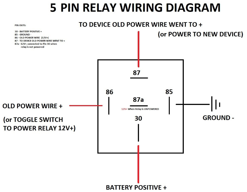
Wiring a four-pin relay is a simple three-step process: Connect a 12V battery to Pin 30 of the relay via fuse Connect Pin 85 to the ground Pin 86 and Pin 87 are to be used as switching pins Procedure to Wire a Four Pin Relay?

Automotive Fused Relay 40A SPST MGI SpeedWare
How To Wire An Automotive Relay Switch, With Diagram, 4 Pin Wanderlost Overland 59.2K subscribers Subscribe Subscribed Share 180K views 3 years ago Quick and easy way to wire a relay to.
12v 40a Relay 4 Pin Wiring Diagram Naturalfer
Learn how to wire a 4 or 5 pin relay with our wiring diagrams and understand how relays work. The Circuit Protection Specialists. Phone: +61 3 9521 6133 Web: www.swe-check.com.au . Login. Circuit Protection and Power Distribution. Phone: +61 3 9521 6133; Free shipping $150+ Over 7000 products. 4 Pin Relay 4 pin relays use 2 pins (85 & 86) to.

Relay Wiring Diagram 4 Pin Diagram Wiring Diagram For 4 Pin 30 Amp 12 Volt Full Version Hd
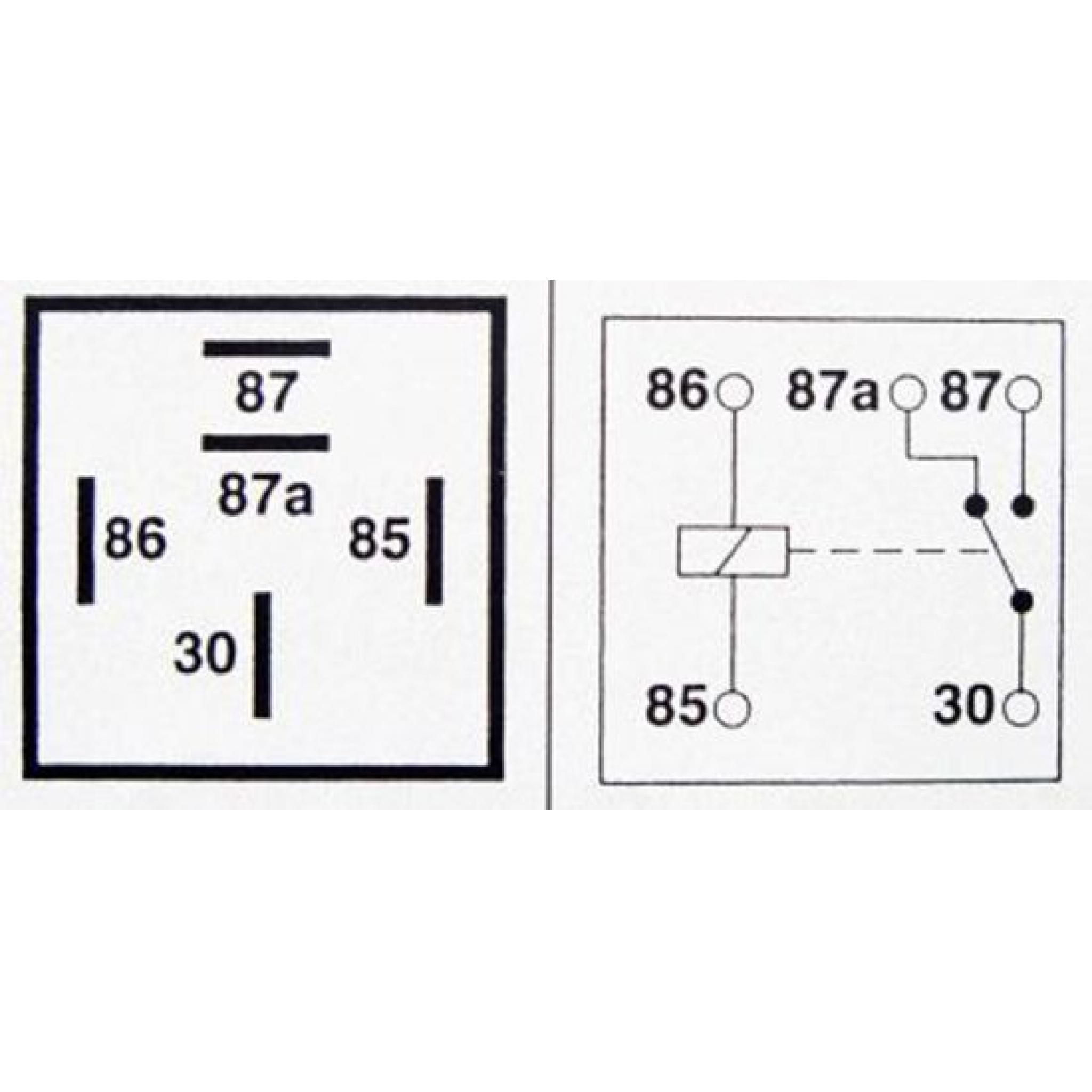
4 Pin relay terminals (SPST) Relays with double throws (two positions) have one extra pin called NC: 5 and 8 pin relay. 5 Pin relay terminals (SPDT) Note: Having an NC terminal means there's a possibility for one more configuration or circuit when the coil is not energized.

12v Relay Wiring Diagram 4 Pin Wiring Draw And Schematic
In a 12v relay wiring diagram 4 pin, each relay is represented by its own symbol. Connections between each of these components are represented by arrows that show the current flow. Each line in the diagram represents a wire or conductor. This makes it very easy to trace out the lines, identify their purpose, and understand the overall system.

4 Pin Relay Wiring Diagram For Lights
To understand the 4 pin indicator relay wiring diagram, you start from the left side of the diagram. You can see the N.O., N.C., Coil, and Common pins. The diagram shows the source of the electricity and its connections to the other pins in the relay. This allows you to properly configure the relay and its connections which ultimately ensures.
4 Pin Relay Diagram EdrawMax EdrawMax Templates
January 31, 2022 Leela Prasad Relays are one of the essential components of modern electrical systems. A is nothing but an electromechanical switch in the sense that a mechanical contact toggles between ON and OFF states due to an electrical signal.

Diagram For Wiring A Relay
Step 1. Get Prepared Stripping The Insulation Of Relay Wire Strip for one inch of the insulation from the end of all wires of the relay. Figure out the coil and high-amperage circuit terminals.

Relay Wiring Diagram 4 Pin Diagram Wiring Diagram For 4 Pin 30 Amp 12 Volt Full Version Hd
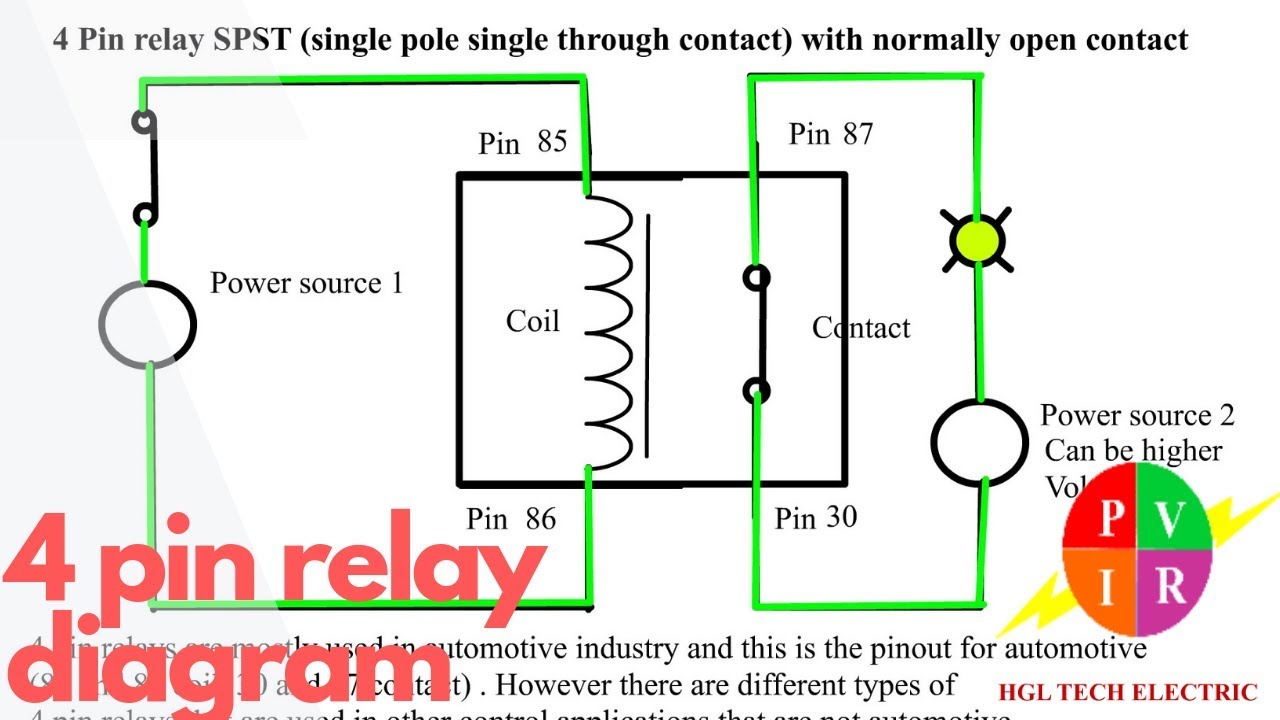
4 pin relay diagram. 4 pin relay wiring. 4 pin relay animation. 4 pin relay connection. 4 pin relay with SPST normally open contact.Featured websites: https:.

Understanding The 4 Pin Relay Wiring Diagram For A Horn WIREGRAM
how to wire a 4 pin relay.Equipment used in the filming is Gopro Hero 8 fromhttp://Gopro.comOthe equipment used for filming is the iSteady gimble fromhttp://.

12v 30a Relay 4 Pin Wiring Diagram Wiring Digital and Schematic
By following a complete diagram guide, you can easily wire a 4-wire relay in your electrical system. First, it is important to identify the control terminal, which receives a low-voltage signal to activate the relay. This terminal is usually labeled with an "C" or "Coil" symbol.
Relay Wiring Diagram A Complete Tutorial EdrawMax
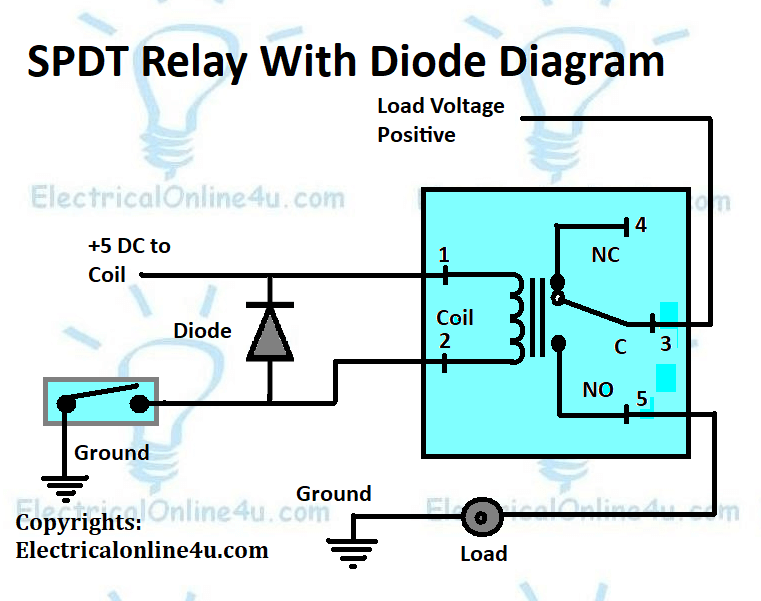
A simple wiring diagram of a relay is shown here to help you understand how it works in a circuit. Relay wiring diagram Let's talk about this relay wiring diagram now. It is the relay that is powered by the DC supply.

4 Pin Relay Diagram 12 Volt Car Relays Used In Automotive Industry / Smallest size (10.2 × 18.
In this article, we will provide wiring diagrams of 4 pin and 5 pin automotive relays to help you better understand the wiring process. We'll start with a brief overview of what relays are and why they are important for your electrical system.
Denso 4 Pin Relay Diagram
The wiring diagram for a 4 pin flasher relay is relatively simple. The following diagram shows the basic wiring for a flasher relay that is used to control two lights: [Image of a 4 pin flasher relay wiring diagram] As you can see, the positive terminal of the battery is connected to terminal 3 of the relay.

10+ 4 Pin Relay Wiring Diagram Robhosking Diagram
A 4 Pin micro relay wiring diagram will usually show the diagram symbol and its associated label, the wire number and color code, the list of contacts or coils, the wire ratings and ampacities, the terminal number, and the overall drawing. It may also include items such as dimensions, pinouts, and mounting holes for connection points.
Automotive Relay Wiring Diagram
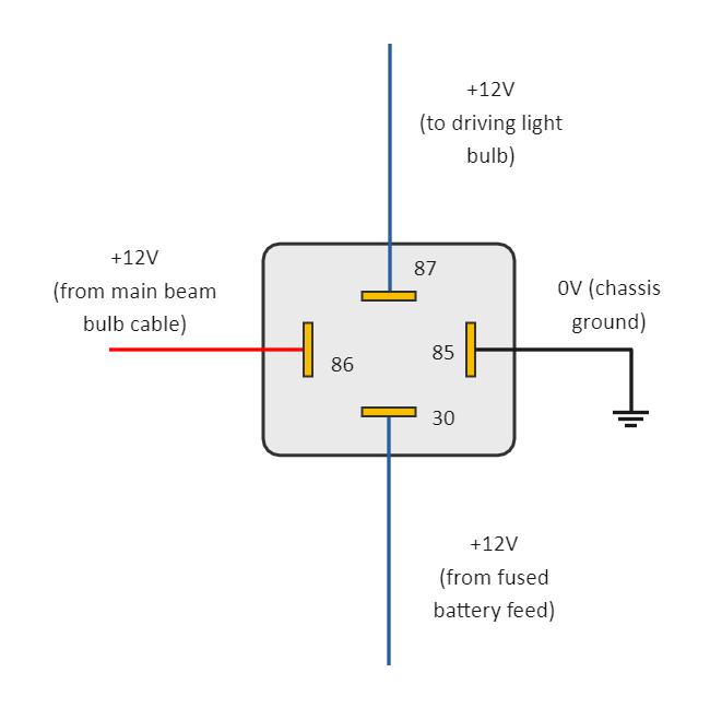
1. Identify the wires of Headlights: The first step in order to wire the relay for the driving light is to identify the wires coming out of the driving lights. Normally, there are two wires connected to these lights out of which, one is the power wire, normally having a red color, and another one will be ground wire black in color. 2.
